
Quality
Starrett KMR-200 video inspection system strengthens dimensional verification
Our Starrett KMR-200 video measuring system gives non-contact, sub-millimetre dimensional verification of moulded silicone components, with DXF overlay comparison straight against the customer drawing.
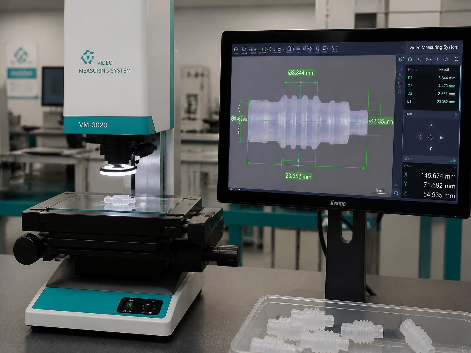
Measuring a moulded silicone part is harder than measuring a machined one. The material deflects under a probe, thin walls distort under the lightest contact, and the features that matter most, sealing lips, membrane thicknesses, valve slits, are exactly the ones a mechanical gauge is worst at reading. Our Starrett KMR-200 video inspection system removes contact from the equation entirely.
The KMR-200 sits in our inspection area alongside the moulding cells, and is used for first-article inspection, in-process dimensional checks, tool trial assessment and routine batch verification of components produced in our ISO 8 cleanroom.
Why non-contact measurement matters for silicone
Liquid silicone rubber typically moulds at 30 to 70 Shore A. Any contact-based measurement applies a load, and any load on an elastomer produces a reading that reflects the gauge pressure as much as the part. On a 0.4 mm membrane or a compression-sealing lip, that error can be a meaningful share of the tolerance band.
Optical measurement avoids that problem. The part sits unloaded on a glass stage, the camera reads the edge, and the dimension recorded is the dimension the part actually holds in its free state, which is the condition the drawing usually specifies.
Up-light and down-light: separating the part from the flash
The KMR-200 carries both surface (ring) illumination above the part and transmitted (sub-stage) illumination through the glass stage, and the combination is where the system earns its keep on moulded silicone.
With down-lighting alone, a moulded part and its flash present a single, continuous silhouette to the camera, the thin film of flash that trails the parting line reads as part of the component, so an edge that should sit at the moulded boundary is measured out at the edge of the flash. On a critical sealing dimension that error can be a large share of the tolerance, and worse, it is inconsistent from shot to shot.
Switching to up-lighting (transmitted illumination from beneath the stage) changes what the camera sees. Light passes through the translucent silicone body but is blocked by the denser moulded material, so the true moulded profile is picked out sharply while the thinner, less opaque flash reads differently and can be visually and measurably distinguished from the part itself. The edge the system locks onto is then the actual moulded edge, not the flash that trails it.
This is a genuine benefit for medical silicone work. Flash is an inherent feature of LSR moulding, even a well-vented tool leaves a thin film at the parting line, and it is rarely uniform. Being able to distinguish the moulded part from that flash optically, at magnification, means:
- True dimensions, not flash-to-flash measurements: the recorded edge is the moulded boundary, so sealing diameters, wall thicknesses and critical lengths reflect what the tool actually produced.
- Earlier flash detection: during tool trials, the contrast between part and flash makes venting and clamp issues visible immediately, well before they would show up in a written inspection report.
- Consistent measurements batch to batch: because the method does not rely on the operator visually deciding where "the part ends," results are repeatable between people and across time.
In short, the dual-illumination capability turns what would be a judgement call under a conventional vision system into an unambiguous, repeatable measurement, which is exactly what an ISO 13485 inspection routine needs.
System configuration
- Precision 200 × 100 mm (8" × 4") XY measuring stage
- MetLogix™ M3 measurement software with Digital Comparator
- Colour digital video camera with 6.5:1 zoom lens
- Auxiliary 0.5× and 2× lenses for extended field of view and fine detail
- LED ringlight (surface illumination) and sub-stage transmitted illumination
- Automatic video edge detection
- 24" touchscreen operation at 1920 × 1080
DXF overlay: measuring against the drawing itself
The capability that changes day-to-day working practice is DXF import. The customer's CAD profile is loaded directly into the M3 software and overlaid on the live image of the part, so the moulded geometry is compared against the nominal profile rather than against a list of numbers transcribed from a drawing.
In practice this shortens tool trial assessment considerably. Where a profile deviates, shrinkage on a long dimension, a slightly proud parting line, a radius that has not filled, it is visible immediately, in the right place, at magnification. That feeds straight back into tooling correction instead of waiting on a written inspection report.
Where we use it
- First article inspection: full dimensional verification of T0 and validation samples against the customer drawing
- Tool trial and correction: rapid profile comparison to guide steel adjustment before validation
- In-process checks: scheduled dimensional sampling during production runs, recorded against the batch
- Goods-in verification: inspection of bought-in components and inserts used in overmoulding and assembly
- Investigation work: evidence-based root cause analysis when a dimension drifts
Inspection within the quality system
The KMR-200 is managed as controlled measuring equipment under our ISO 13485:2016 quality management system, with defined calibration intervals, documented measurement routines and results recorded against batch traceability records. Inspection routines are written during process validation and then run consistently for the life of the programme, so results remain comparable batch to batch and year to year.
Get in touch
If you have a component with features that are difficult to verify by contact methods, or you would like to review the inspection approach for an existing programme, contact the CPT engineering team.