
Technical Guide
Liquid silicone rubber moulding: a complete guide for medical device engineers
A practical walk-through of the liquid silicone rubber (LSR) moulding process, from material chemistry and tool design to cure kinetics, cleanroom integration and validation, written for design engineers specifying silicone components for regulated markets.
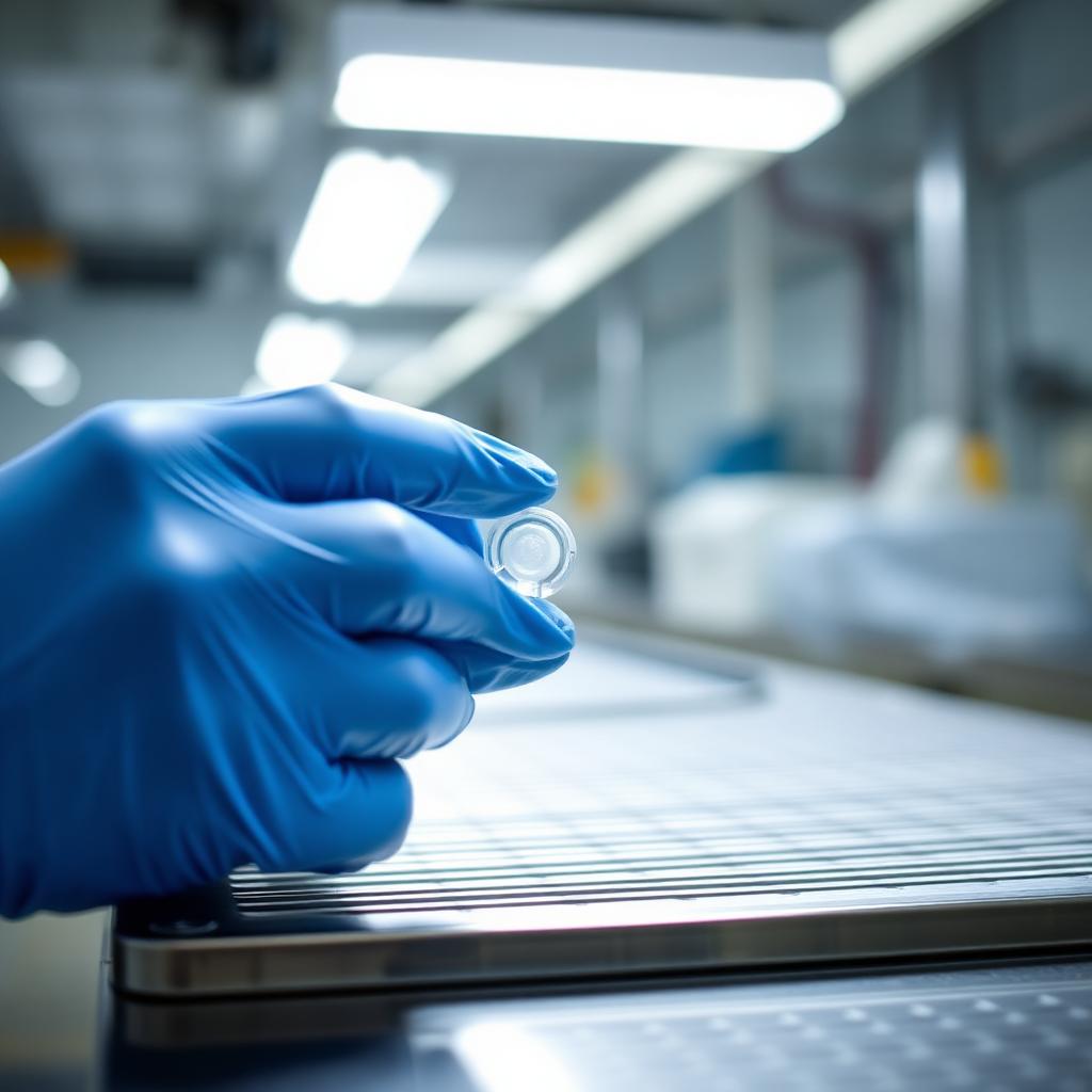
Most medical silicone components sold today are moulded from liquid silicone rubber. It is the process we run day in, day out, and this guide is our attempt to set out, plainly, how it works, where it earns its place, and the design decisions that quietly determine whether a part reaches production on time and on budget.
The notes below are written from the shop floor rather than from a textbook. They reflect what we see running validated LSR programmes for regulated customers under an ISO 13485:2016 quality system in an ISO 8 cleanroom, the failure modes we watch for, the trade-offs we walk customers through at design freeze, and the details that are easy to miss until a tool is already cut.
What is liquid silicone rubber?
LSR is a two-component, platinum-catalysed silicone elastomer supplied as two low-viscosity pastes, labelled Component A and Component B, that are metered, mixed and injected into a heated mould where they crosslink into a solid elastomer. The chemistry sits in the polydimethylsiloxane family, with vinyl-terminated polymers reacting with silicon-hydride crosslinkers in the presence of a platinum catalyst.
Two properties dominate why LSR is chosen for medical work:
- Biocompatibility. Medical-grade LSR grades from Wacker (Elastosil), Shin-Etsu (KE-series), Momentive (Silopren) and NuSil (MED) carry USP Class VI and ISO 10993 support from the raw-material supplier, and implant-grade sub-families are available for greater-than-29-day contact.
- Processing stability. Because the material arrives at the press as a liquid, cavity fill is highly repeatable, cavitation can be pushed high (32-, 64- and 128-cavity tools are common), and the process window is wide enough to run through-the-night without operator intervention.
Contrast this with high-consistency rubber (HCR), which is supplied as a solid gum, calendered into strips, and either compression- or transfer-moulded. HCR remains the right choice for very large parts and certain implantable geometries, but for anything requiring dimensional precision at volume, LSR wins.
How the LSR moulding process works, step by step
A production LSR cell has more moving parts than a conventional thermoplastic moulding line. Each stage matters:
1. Material handling and metering
Components A and B arrive in matched 20 kg pails or 200 kg drums. A hydraulic follower plate presses each component out of its pail into a static mixer at a strictly controlled 1:1 ratio. Any drift from 1:1 shifts the crosslink density, changes the durometer of the finished part, and, at extremes, leaves un-crosslinked silicone in the mould. Modern metering units close-loop the ratio and alarm at ±1% deviation.
Pigment (typically a medical-grade masterbatch) is metered as a third stream at 0.5–2% loading. The three streams pass through a static mixer, which is intentionally short, the material must reach the injection barrel without initiating cure.
2. Injection into a heated mould
Unlike thermoplastic injection moulding, which injects hot melt into a cold mould, LSR is the opposite: cold material into a hot mould. Barrel and cold-runner temperatures are held around 15–25 °C to prevent premature cure, while the mould itself is heated to 160–200 °C to drive crosslinking.
Cavity fill is typically 1–3 seconds. The material's low viscosity means it flashes readily, flash faces on medical LSR tooling are cut to 5–10 µm, well tighter than a comparable thermoplastic tool. Vacuum-assist is standard: air trapped in the cavity produces voids and short-shots, so the tool is evacuated to a few millibar before injection.
3. Cure in the mould
Cure time depends on part thickness, mould temperature and the specific grade, typically 20–90 seconds for wall sections between 1 and 4 mm. The exotherm is modest, so cure is limited by heat transfer into the part rather than by reaction rate. Thick sections (above ~6 mm) become uneconomic on a fast-cycle press and are usually redesigned into thinner geometry or moved to HCR.
4. Demould and separation
Because LSR is a low-friction elastomer, parts often demould without ejector pins. Robotic pick-and-place, brush-off systems and blow-off nozzles separate parts from runners and drop them onto a cleanroom-side conveyor. Cold-runner systems keep the runner material liquid, there is no runner regrind in an LSR cell, which is one of the reasons the process integrates well into a cleanroom environment.
5. Post-cure (where required)
Many medical LSR programmes specify a post-cure, typically 4 hours at 200 °C in a batch oven, to drive off residual volatiles and stabilise the extractables profile. Post-cure is not always required (platinum-cure LSR is comparatively clean out of the mould), and modern grades increasingly avoid the requirement altogether. Whether it is needed is a specification decision informed by the extractables and leachables study, not a default.
Design for manufacture, the rules that matter
Most preventable LSR failures are locked in at design freeze, not on the shop floor. The rules below are the ones that recur most often on new programmes.
Wall thickness and uniformity
Aim for wall thicknesses between 0.5 mm and 4 mm, ideally uniform across the part. Thick sections cure slowly and can leave uncured material at the core; thin sections can short-fill. Where a step change is unavoidable, blend it with a generous radius rather than a sharp transition, flash and voids concentrate at abrupt geometry changes.
Draft angles
LSR needs less draft than thermoplastics, 0.5° is often sufficient, and zero-draft is possible on short walls. Over-drafting a silicone part costs cavity space and rarely delivers a demould benefit.
Undercuts and complex geometries
LSR's elasticity is a genuine design freedom. Parts can be pulled off undercuts that would require a side-action or slide in a thermoplastic tool, provided the undercut is within roughly 5–10% of the local diameter and the material's tear strength supports the extraction. Duckbill valves, self-sealing septa and one-way check features exploit this daily.
Parting line placement
Sealing surfaces, valve faces and any feature the customer will inspect visually must sit away from the parting line. Even a well-cut LSR tool leaves a witness on the parting line, invisible to the eye but detectable under vision inspection at 20× and above.
Tolerances
Practical general tolerances on medical LSR mouldings sit around ±0.05 mm on features under 10 mm and ±0.5% on larger dimensions. Critical dimensions can be held tighter with cavity-by-cavity dimensional mapping and steel adjustment during tool try-out, but the effort scales quickly. Applying ±0.02 mm to every dimension on the drawing is the fastest way to make a part uneconomic to produce.
Shrinkage
LSR shrinks 2.0–3.5% on cooling from mould temperature to room temperature, depending on the grade, the durometer and the constraint imposed by the part geometry. Shrinkage is anisotropic and non-uniform on ribbed, cored or overmoulded parts. Reputable tool-makers use their own compensation data, do not rely solely on the material data sheet.
Tooling considerations
An LSR tool is a precision-engineered piece of machinery in its own right. Expect the following on a medical-grade cold-runner tool:
- Cavity steel: hardened stainless (typically 420 or Stavax) polished to a controlled Ra, sometimes with a PVD coating on high-cavitation tools to extend life.
- Cold-runner block: actively cooled to keep the material below cure onset while the cavities run at 180 °C. Nozzle needles open per shot to inject the calculated volume into each cavity.
- Vacuum sealing: the entire cavity is sealed by a perimeter O-ring so the cavity can be evacuated before injection.
- Heating and cooling zones: independently controlled to hold cavity temperature to ±2 °C across the tool face. Uneven cavity temperature produces uneven cure and cavity-to-cavity dimensional variation.
- Automation interface: parts are typically picked from the mould by an EOAT (end-of-arm tooling) that lifts the runners and parts simultaneously, then hands them to a downstream separator.
Tool lead times for medical LSR are typically 12–18 weeks from steel to first-off, depending on complexity. Attempting to compress this is the second most common source of programme delay after design changes late in the process.
Cleanroom integration
Medical LSR moulding almost always runs in a cleanroom, most commonly ISO 8 (Class 100,000) for Class I, IIa and IIb components. LSR is a well-behaved process from a particulate standpoint, no drying, no purge, no regrind, but the surrounding operations (insert loading, dimensional inspection, primary packaging) drive most of the environmental risk. Read our companion article on what ISO 8 really means for the operational side of that discussion.
Validation, IQ, OQ, PQ for an LSR process
A medical LSR programme is not validated by a single set of documents but by a coordinated evidence chain that spans the tool, the machine, the process and the product:
- IQ (Installation Qualification): the tool, press, cold runner, robotics and downstream automation are installed and documented to specification.
- OQ (Operational Qualification): the process window is explored at the boundaries. Cavity pressure, injection speed, mould temperature and cure time are varied to establish the edge-of-failure envelope, and the operating point is chosen well inside it.
- PQ (Performance Qualification): three consecutive production lots are run at the validated operating point and characterised against the full acceptance criteria. From here forward, the process is locked; any change re-opens the validation.
The output of the validation is not just a certificate but a defined operating point with SPC control limits, a change-control regime and a data record that the customer's regulatory team can incorporate into their technical file.
Cost drivers on an LSR programme
The three cost levers on an LSR programme, in order of impact:
- Cavitation. Doubling cavitation roughly halves piece price at high volume, up to the point where cycle time or automation limits it. This is the single largest lever on unit cost.
- Cycle time. Driven by wall thickness and cure temperature. Redesigning a 5 mm wall to 2.5 mm can halve the cycle at the cost of a small mould change.
- Secondary operations. Every additional step after moulding, coating, plasma treatment, subassembly, printing, carries fixed setup and running cost. Consolidating operations into the moulding cell (in-mould decoration, insert overmoulding) frequently pays for itself.
The unhelpful advice, "reduce material cost", is almost never where the value sits on an LSR programme. Medical LSR grades cluster in a comparatively narrow price band; the cost lives in the tool, the cell layout and the design.
When LSR is not the right answer
For completeness: LSR is not universally the correct choice. Consider alternatives when:
- The part is very large and low-volume, HCR compression moulding is likely more economic.
- The service temperature exceeds 250 °C for extended periods, fluorosilicone or specialist grades are needed.
- The chemistry demands aromatic-solvent resistance, silicone as a family is not the right elastomer.
- The volume is so low that tool amortisation dominates the piece price, some prototype and low-volume programmes are better served by cast or 3D-printed silicone until a market case for tooling exists.
Working with a specialist
The overwhelming majority of avoidable cost on a medical LSR programme is designed in during the specification phase and then paid for over the life of the product. Engaging a specialist moulder during design, not after, is the single most reliable route to a part that meets its acceptance criteria and can be produced repeatably.
Get in touch
To discuss a new silicone programme, a second-source qualification, or a legacy tool that is not performing in line with expectation, please contact the CPT engineering team.